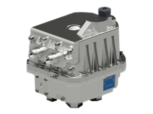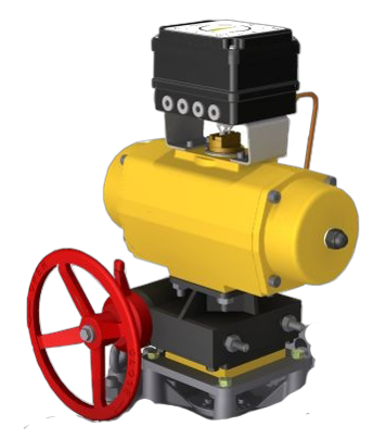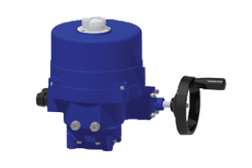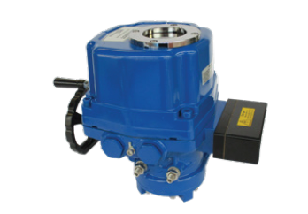
Details
- Power: 24 VDC
- Key Features & Benefits: High vibration and shock resistance *Increased operating temperature range *Hazardous location options available *Manual override fitted to non-hazardous area version - valve can be operated in event of power failure *Software is configurable for varying applications *CAN bus communication *Improved Duty Cycle
EH - Meets military requirements
For the electrically operated valves, a number of actuator options are available, which use an electric motor that rotates in either direction in response to the ON-OFF signals received.
The motor drives a gearbox connected to the rotor shaft and turns the valve rotor clockwise or counter-clockwise, a maximum of 90 degrees. At the end of travel, limit switches are incorporated to isolate the electrical supply to the motor when the valve rotor has reached either end of the rotation. A feedback hall sensor is available on some actuators, providing position indication to the control system.
Most actuators are powered by an electric motor driving a worm-type gearbox. The worm gearbox prevents reverse drive due to the forces generated by fluid flow. A thermal cutout is fitted preventing overheating. Limit switches at each end of stroke disconnect motor power when end stroke is reached. These can also be used for remote indication.
See page 12 for more information on the electric actuator options


