
How to achieve the right system temperature with TCV
About TCV
TCV are internal-sensing, 3-Way thermostatic control valves, or temperature regulators, suitable for process control and industrial applications where fluids must be mixed or diverted depending on their temperatures. Simple to install, operate and maintain, they provide years of trouble-free, reliable temperature control without the need for external power sources. AMOT 3-Way thermostatic control valves are the perfect “fit and forget” solution in cooling lubricating oil, engine jacket water, heat recovery and tempered water applications.
Proven
TCV valves have over 50 years of proven performance in
marine, power generation and oil and gas applications.
General information about TCV
The TCV is a direct-acting self-actuated 2 or 3 way temperature control valve. The regulation takes place automatically as a result of the temperature of the liquid flowing through the valve.
The main advantages of TCV are:
a) Simple, proven and robust.
b) No need for EL, pneu or control system.
c) Withstands a lot of vibrations and shocks.
d) Explosion-proof – ATEX.
e) Low fiddle risk.
f) No capillary tubes to step on.

AMOT produces more than 10 different TCV models that in principle have the same function, but somewhat different design: size, configuration, pressure drop, flange or threads etc. Table below shows the flow interval for the most common TCV models.

1. DN40 - DN50 BO with threads
2. DN50 - DN200 BO with flanges
3. DN50 BF with flanges
4. DN50 BH with threads, high pressure
5. DN50 - DN200 BR with flanges and manual override
6. DN15 - DN200 TCV for salt water
7. DN15 – DN40 C with threads
8. DN40 CF with flanges
9. DN200 D replacement
10. DN15-DN40 E with threads
11. DN 15 – DN40 E with flanges with or without man.o.ride
12. DN20 J with threads
13. DN 20 – DN80 R butt weld
14. DN 100-150 H with flanges with or without man.o.ride
15. DN25 2470 External sensing with threads
16. DN100 4500D with flanges
17. DN50 20100D with flanges
18. DN100 47466X with flanges for Yanmar
19. 48066X with flanges
The most commonly used model is the B, which is available in diameters from DN40 to DN200 for freshwater/glycol, seawater and oil, among other fluids.
1. Operation of the TCV
Port A is always open.
Two other gates regulate successively, linearly and in parallel, so that one opens correspondingly when the other is closed. Example of connection for temperature control of motor:
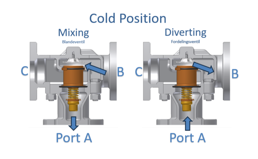
Port A connects to motor, port C to cooler and port B connects to bypass cooler. The TCV can be used as a mixing valve Hot cooling water (typically from the engine) into port B and chilled water (from the cooler) into port C.

The TCV can be used as a distribution valve: Cooling water colder than setpoint out of port B and water hotter than setpoint out of port C.
Can be used in a 2-way water saving application. Valve minimizes flow through cooler to save water and energy. The solution requires an internal leak hole to ensure a small flow through the valve so that the valve can continuously sense the right temperature.

The TCV can regulate the cooling of heating systems (e.g. an engine) or regulate the heat of cold systems (e.g. evaporation of LNG). The TCV should only be used for liquids, not gas or slurry. The TCV set temperature is supplied from 14°C to 116°C in increments of 2-3 degrees, but the set temperature must be set before installation and
can only be changed when changing thermostatic elements, but not by adjusted during operating.
TCV is available in many materials and can be used for many different liquids, most common are:
a) Freshwater glycol
b) Seawater
c) Oil
Manual override (the option of manual forced opening) is selectable for several TCV models, including model B.

2. How the thermostatic elements work
Illustration shows thermostatic elements for model B, i.e. 1096X for valves without manual override and 2433X for valves with manual override.
3. Flow through the valve when system temperature is at least 5
degrees colder than set temperature
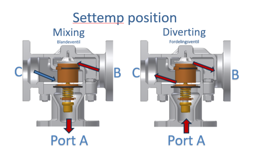
4. Flow through the valve when system temperature equals set
temperature
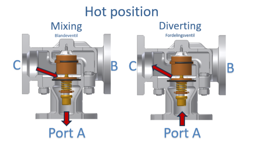
5. Flow through the valve is when the system temperature is at least 5 degrees warmer than the set temperature
6. Ideal flow across ports B and C at different temperatures
The table below shows how much flow there should ideally be over ports B and C at different temperatures. Mentions in particular the following three temperature levels:
>5 degrees colder than settemp: B is 100% open and C is 100% closed.
Settemp: B is 50% open and C is 50% open.
>5 degrees warmer than settemp: B is 100% closed and C is 100% open.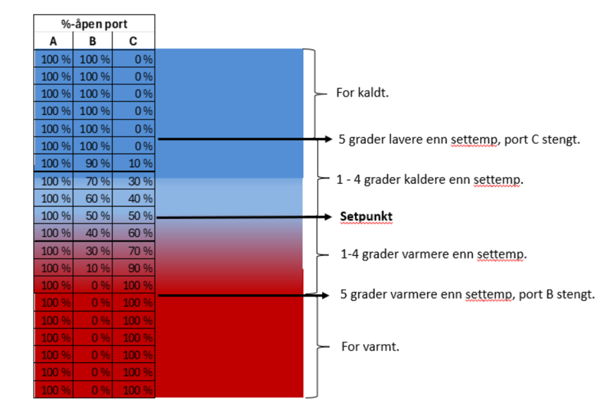
7. Actual flow deviates from ideal flow over ports B and C
It is common for the actual flow over port C to be lower than ideal, it is usually due to a higher pressure drop over the cooler, compared to the pressure drop in the bypass run. It is not uncommon for the pressure drop above the cooler to be 0.3-0.4 bar. Furthermore, there is a risk that the pressure drop over the cooler will increase over time as a result of fouling in the cooler. It is possible to increase the pressure drop over the bypass barrel by an orifice as a measure to minimize differences in pressure drop across the B and C ports.
8. General information about leakage
Leakage can be the result of corrosion, material cracks or broken gaskets. External leakage will be easily detected by visual inspection and is most often due to defective or missing seals. Internal leakage can easily be detected by measuring temperature as described below.
9. Wanted Internal Leak Over Closed Port - Leak Hole
In some systems, there is a need for a small flow over a closed port, this is solved by drilling leakage holes as follows:
a) Wanted leak over gates A – B: Drill holes in the thermostat element.
b) Wanted leak over ports A – C: Holes are drilled in the valve body.
The diameter and number of holes are adapted to the wanted flow, see data sheet for how this is specified in the valve´s model code.
LINK TIL DATASHEET??
10. About Unwanted Internal Leak Over Closed port
Leakage over closed port B is undesirable because cooling of the system takes longer, and requires a larger flow over the cooler, if hot water leaks in from the bypass course. Leakage over closed port C is undesirable because heating the system takes longer, and requires more heat, if water leaks in from the cooler.
The TCV is designed to minimize internal leakage to near zero. It takes a significant differential pressure across a closed port to achieve an internal leak of any significance.
11. Unwanted internal leak over closed port B
When system temperature exceeds set temperature by 5 degrees, port B should close completely. This is done by the thermostat element pressing against the seat with a significant amount of pressure, see illustration above.
12. Unwanted internal leak over closed port C
When system temperatures 5 degrees lower than set temperature, port C should close completely. This is done by the thermostat element closing with a significant amount of pressure, see illustration above.
13. Internal leakage not relevant when valve regulates
When system temperatures within the valve´s control range, which are 4 degrees below and above set temperature, the significance of internal leakage can be disregarded, because the differential pressure over the seal becomes close to zero.
14. Energy balance: too hot or too cold
TCV´s function is to regulate the right amount of chilled water.
If there is not enough heat available in the system to achieve settemp, then the system temperature will balance at a lower level than desired. The TCV can then do nothing but reduce the cooling to zero. If there is not enough available cooling capacity in the system to achieve set temperature, then the system temperature will balance at a higher level than desired. TCV can then do nothing but control all flow
through the cooler.
15. AMOT´s recommendation for cooler sizing
AMOT recommends that the cooler capacity be dimensioned so that the wanted system temperature balances at the valve´s set point. This is because then there will be maximum margin against the system temperature ending up balancing at a higher, or lower, temperature than desired.
A consequence of the recommendation is that a cooler must be installed that has enough capacity at 50% of the system´s flow. Due to space considerations, weight and economy, it may be desirable to design with a smaller cooler that will require e.g. 80% of the system flow to balance the system temperature to the right level. This means that the valve´s set point must be set to 2-3 degrees lower than the wanted system temperature.
Technically, these solutions can work well, but there is a greater risk that the system temperature balances at a higher level than desired.
The cause of too high a system temperature can be:
a) Errors and shortcomings in design and engineering: In a large system, there may be several units that supply and consume heat,
b) Wrong assumptions: It is assumed that the vessel will sail in cold water with a low ambient temperature, but will end up in, for example, the Gulf of Mexico.
c) Groe: Groe means that the cooler has a lower efficiency and a greater pressure drop.
16. How to measure the size of the flow over ports B and C, respectively, and measeure the size of any internal leak over closed port
It is easy to determine how much flow there is over each port by measuring temperature in the following 4 places) Pipe connected to port A, minimum 80-100 cm from valve.b) Pipe connected to port B, minimum 80-100 cm from valve.
c) Pipe connected to port C, minimum 80-100 cm from valve.
d) Pipe connected to cooler on opposite side, compared to valve, minimum 80-100 cm from cooler.
There is a spreadsheet model that calculates the flow across each port and indicates the size of any internal leakage, regardless of whether the valve is installed as a mixing or distribution valve.