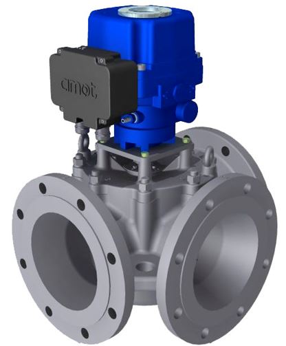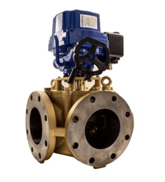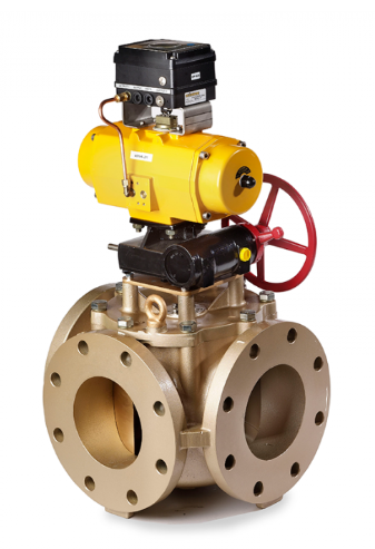
Pneumatic actuator
In addition to pneumatic actuator, it is common to have positioner that make it possible to control with a 4 - 20 mA signal and get feedback on the rotor's position. In addition, manual override is an option. Read more about pneumatic actuators here
The GPD and GG valve with pneumatic actuators is a very robust solution, which meets strict requirements, including:
- Vibration resistant, as well as tolerance to shocks.
- Withstands higher system and ambient temperatures compared to EL actuators.
- Explosion-proof.
- Fail safe is an option.
Dimensions
Please see data sheet page 7 for dimensions per valve size. View datasheet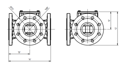
Control system
The pneumatic valve uses a spring return pneumatic actuator and positioner to control the rotation of the valve in response to an input signal for a pneumatic or electro-pneumatic control system. The pneumatic control system sends a pneumatic signal ranging from 0.21 to 1.03 bar (3 to 15 psi) to the actuator to correctly position the valve rotor to achieve the correct system temperature. The pneumatic control system usually consists of a P+I pneumatic controller, sensor and the necessary air supply conditioning equipment (regulators, filters and water traps).
SG80
The pneumatic valve system incorporates a pneumatically actuated three- ay control valve with controller and integral temperature sensor, the SG80, which can be panel or wall mounted. For more information on the SG80, see page 23. The pneumatic G valve system is ideal when there is a lack of electricity or when a fail-safe system is needed. The pneumatic actuator is a rugged, quarter turn, double piston actuator operating on a scotch yoke principle.
The actuator is fitted with spring return as standard allowing fail-safe configuration if necessary. It is also fitted with a valve positioner enabling accurate and repeatable movement. See page 13 for more information on the pneumatic actuator.
Siemens Sipart PS2
Alternatively, Siemens Sipart PS2 positioners can be mounted. Read about https://ingwestad.com/no/productlist/siemens/
GPD - standard design
GPD valves are 3-way ACV: temperature control valves consisting of a powerful rotary valve and a quarter turn PNEUMATIC actuator. GEF is the designation for the same valve body with EL actuator. The GG model is a newer design, but the same dimensions and functionality.
GPD standard design is made for coolants in fresh water/glycol or oil, for system pressure up to 10 bar, design max temp 100ﹾC and max flow 8 750 m3/h.GG standard design is made for coolants in fresh water/glycol or oil, for system pressure up to 10 bar, design max temp 100ﹾC and max flow 770 m3/h. See model GEF/GPD for flow > 770 m3/h.
- Large selection of sizes and materials.
- Flexible port configuration.
- Can be mounted in any direction, including with the actuator pointing downwards.
- Large flow, low pressure drop.
- Small physical size.
Sizes
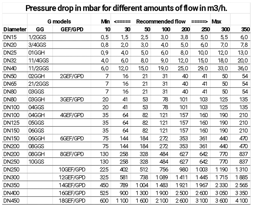
The table below shows available sizes in inches and mm, as well as pressure drop in mbar for different amount of flow in m3/h. AMOT G valves are designed to produce minimal pressure drop. The normal recommendation in sizing the valves is to select a pressure drop between 25 - 300 mbar. The normal recommendation for salt water in bronze valves is a max pressure drop at 100 mbar.
View datasheet for pressure drop values for oil and other fluids with higher viscosity.
Flanges
En1092: PN6, PN10 and PN16.
ASME: 125, 150, 300 and 600lb.
JIS: 5 and 10K.
Max working pressure is 10 barg, unless otherwise stated, regardless of flange type.
About model codes
Page 20 of the datasheet shows how the model code is structured. Below are examples of model code for the standard version.
Model codes for standard GPD (without postioner)
Spec; PN10-16, RF, MAX 10 BAR, CAST IRON, MODE 32, 0.21 to 1.03 Bar (3 to 15 psi) Command signal with manual override.
- 2GPDCBC0E-AA
- 3GPDCBC0E-AA
- 4GPDCBC0E-AA
- 6GPDCBC0E-AA


